Paper mechatronics & automata, or "Paper Mech," encompass a variety of mechanical objects allowing directional motion to be translated into other movements. For example, rotating a crank produces a back-and-forth rocking motion that at first seems separate from the circular motion being used to create it. Automata can be hand powered or operated via motors. PaperMech exist at the intersection of paper, mechanical engineering, and electronics.
Some basic mechanisms include: rack & pinions, cranks, cams, spur gears, planetary gears, and jansen mechanisms.
(text and background only visible when logged in)
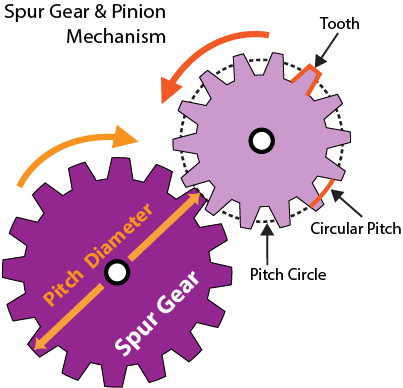
Spur Gear
Spur gears transfer motion from one axis rod to a parallel rod or shaft. The teeth of the gears interlock. When one gear rotates, it causes the interlocking gear and shaft to rotate in the opposite direction.
(text and background only visible when logged in)
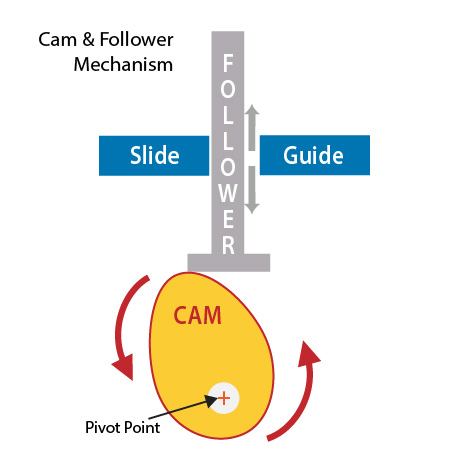
Cam and Follower
A cam and follower mechanism converts rotary motion into reciprocal linear motion. The follower rises and falls as it comes into contact with different points on the rotating cam. It maintains contact with the cam through either the force of gravity or by a spring. The total range of the follower's movement produced by the cam is called the stroke. The motion of the follower is restricted to a pre-determined pattern by a guide and the specific shape of the cam. Pear, snail, and off-center circle cams are common cam shapes.
(text and background only visible when logged in)
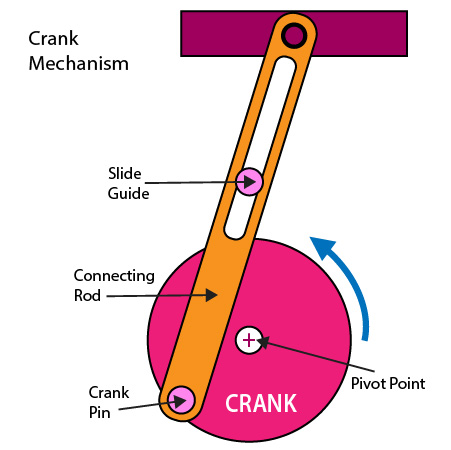
Crank
A crank is an arm attached at a 90° angle to a rotating shaft. When the shaft rotates, the circular motion is translated from the arm into reciprocating motion (repetitive up-and-down or back-and-forth linear motion) of a connecting rod.
(text and background only visible when logged in)
Planetary Gear Diagram
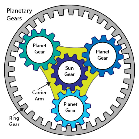
Planetary Gears
Planetary gears consist of multiple gears (planetary gears) attached to a carrier arm rotating around a central gear (sun gear). This structure is enclosed by a large ring gear. Planetary gears allow for faster speeds and greater lubricant retention.
(text and background only visible when logged in)
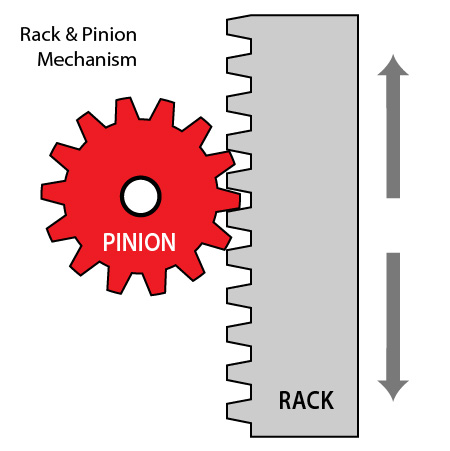
Rack and Pinion
The Rack and Pinion produces linear movement. Within the mechanism, a circular pinion gear engages the teeth of the linear rack. As the gear rotates, the rack travels up and down or side to side, depending on the orientation of the mechanism.